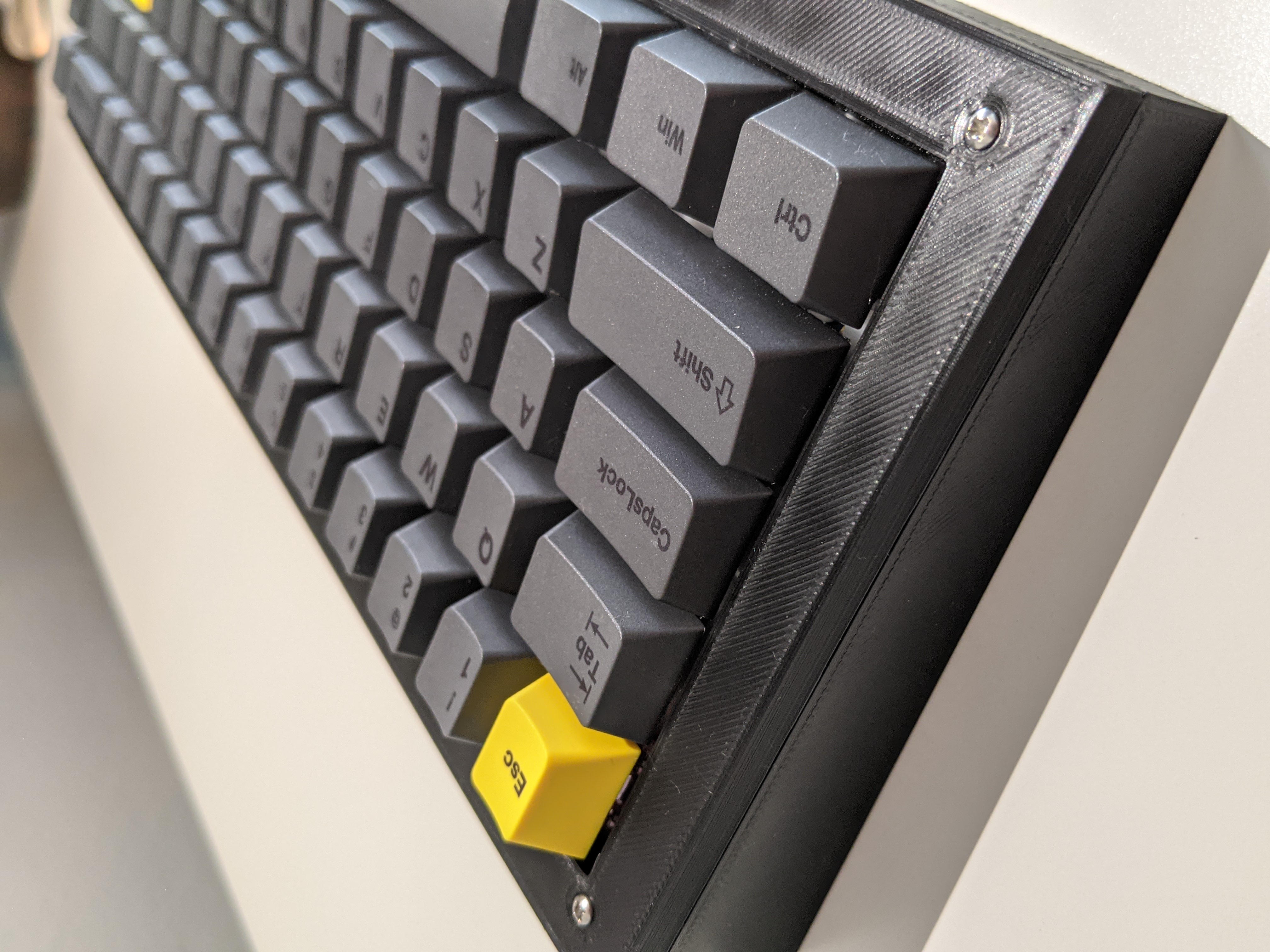
 If you want to make this yourself, all the files and the bill of materials are on my GitHub! (WORK IN PROGRESS!)
Motivation
One of my favorite things in life are specialty tools. I have a specialty pencil that I use for taking notes or exams. I have a nice Santoku that I use for cooking. So if I spend most of my time at a computer, shouldn’t I have a nice keyboard?
That really was the thought process I had when I wanted to get started looking at nice mechanical keyboards. There is a whole hobby surrounded around the creation of specialty keyboards with crazy layouts and specialty materials. Gone are the days of plastic membrane keyboards and here are the all metal keyboard cases, great type feeling, and superior typing sound (theres are strange obsessions with acoustics in the hobby). The custom keyboard scene is pretty obscure, and a hassle to understand as a new hobbyist trying to enter the scene. As well, this hobby can be quite expensive, sometimes reaching over $1000!
From the keyboards I have bought, I haven’t spent that kind of money, but it has been quite a bit more than a standard $10 keyboard from amazon. For my most recent keyboard, I ordered a custom made 65% keyboard from the United Kingdom at https://sidderskb.co.uk/ which was a gasket-mounted stacked acrylic case. Since getting it, I’ve loved the layout, but I’ve had issues with the case; mainly, the aesthetic. It’s not the nicest looking keyboard ever, and paying what I did for it, I wish I could have it look exactly that way I want it to. Being a person that likes to mod and tinker, I wanted to design a case around this keyboard, and improve the way me keyboard looks while retaining the sound and feel of the board. So, I set off on creating my own keyboard case, which ended up being a designing journey of an entire keyboard.
The Plan
For a keyboard, the three major components that make up a keyboard are the case, the plate, and the PCB. For my own board, I needed a plan for designing these three components myself.
Case
I wanted to design a case that was more in line with the tradition high profile case seen below.
Additionally, there are a few constraints that I needed to design around. I wanted to transplant the current pcb and plate to a new case, retaining the type sound and feel, or retaining the gasket mount of the board. Below we can see the different types of mounting styles of a keyboard. Gasket mount sandwiches a mounting plate between two materials that when joined create the case.

In order to transplant to a new case, there is a simple design issue I can design around. In order to retain the gasket mount, placing the pcb and plate into a new case involves designing a case which can sandwich the plate. I must design the new case to accept the current gasket mount points of the plate, which is non-standardized. Other than that specific restraint, I could design the case in whatever form factor I wanted. Brainstorming, I thought through the idea of making specialty additions like a pen rail, but I decided that I should focus on designing to meet my minimum goals before appending those additions.

Plate
In order to create a suitable plate for the keyboard, I needed to find a way to create a design model for manufacturing. The usual route for manufacturing a plate is through the use of a laser cutter as the plate is very thin: on the order of ~1.5 mm. Fortunately, a well known design site, http://builder.swillkb.com/ allowed me to create my own plate using a layout generated from another well known design site http://www.keyboard-layout-editor.com/, and the results can be seen below.

There are a few layouts that keyboards of this size can have, but I went with an arrow blocked version mainly because I love the look. Something about that waste of space looks nice to me. Moving on, the plate now needs a way to mount with the case. Designing my current case around the current gasket plate in my board from SiddersKB, I needed to edit the plate from the plate builder site, and for that I used AutoCAD.
PCB
The PCB is one of the hardest to design pieces of the entire keyboard, so I opted not to design it myself! However, of the 3 main components that make up a keyboard, the PCB is the most universally designed component of the 3. Almost all gasket mounted keyboards utilize different mounting geometry with mostly the same PCB size and layout used every time. Because of this it made the most sense to spend my time manufacturing 2 parts instead of 3. I was slightly disappointed with myself that I wasn’t making my own PCB to truly make this keyboard completely custom, but my friend is willing to design one for me so in the future I’ll have to update with his progress on the custom board.
The off the shelf PCB I decided to go with was the Instant65, since I have had good experience ordering from CannonKeys and using this specific PCB.
Design Stages
Case
Using my design constraints, I went to SOLIDWORKS and began designing. I began by designing the basic shapes of the case, kind of like starting with the raw material needed for a CNC job. Below, there are the three basic shapes with of the case.
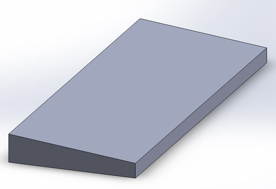
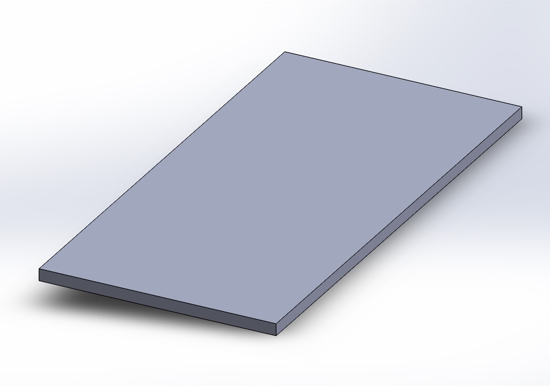
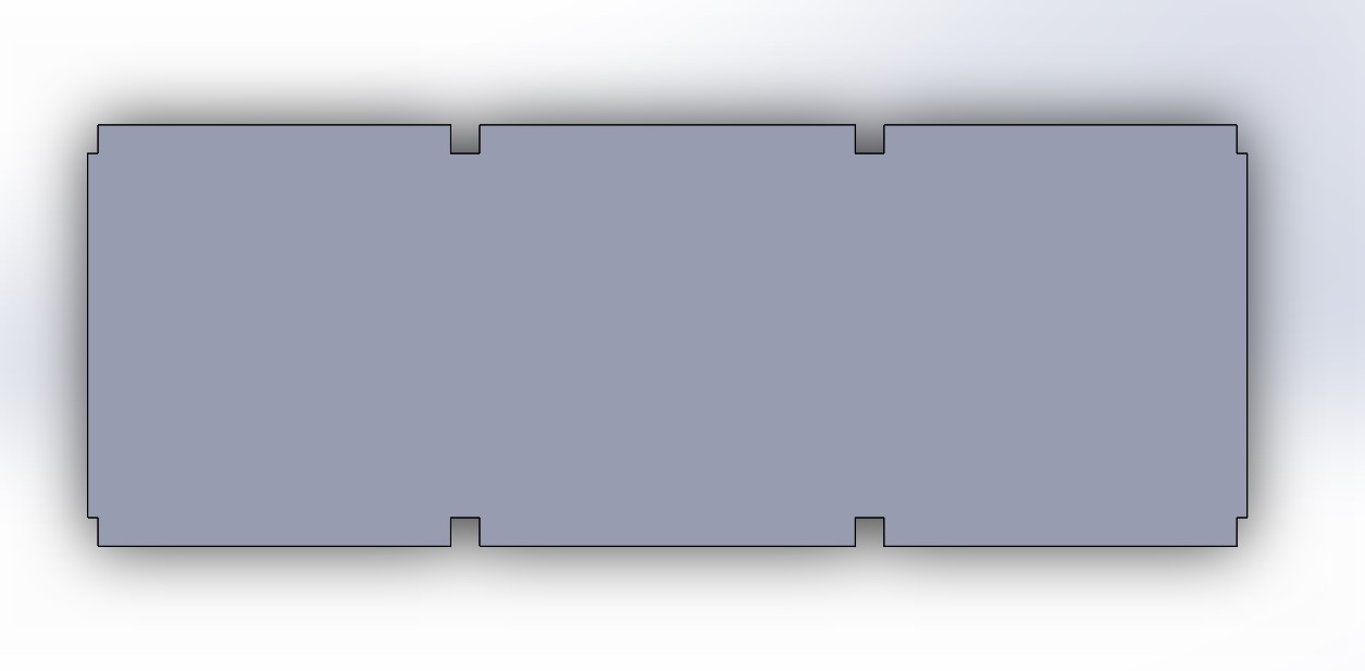
My plan for this board is to design the three major pieces of the board and in the assembly file, cut extrude the necessary components, and export the files for manufacturing. The last image is the profile of the plate, and is the major design constraint for the case. Once the three pieces were created, they were placed into an assembly and cuts were made on the pieces.
Starting with the two case pieces, the bottom piece was cut to house the keyboard plate.
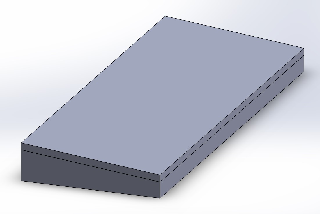
Using the plate from my current keyboard, I used the SOLIDWORKS part to cutout the slot to place the plate.
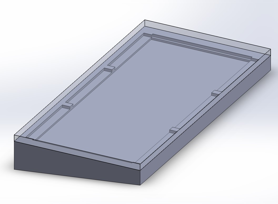
Then, the cutout for the USB-C port was placed, which was measured based on the cutout for my current board.
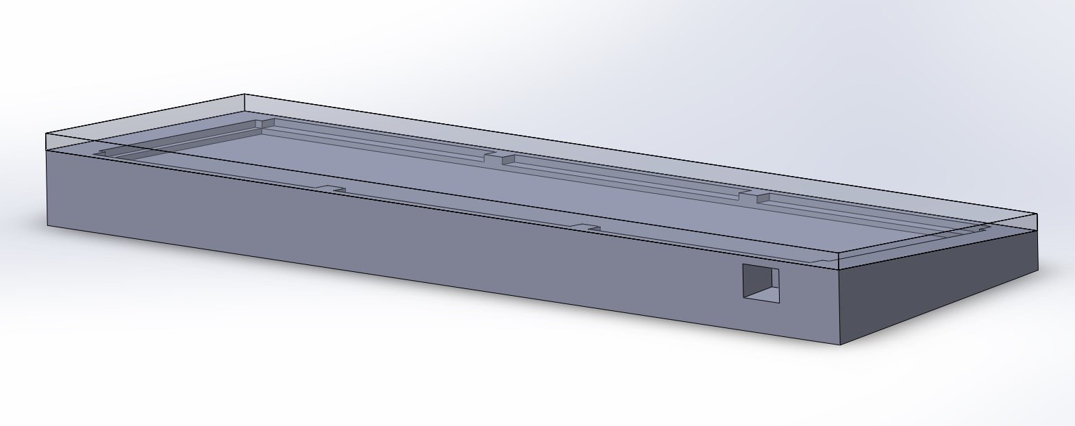
Then, the top piece was cut to allow the key passthrough while including the blocker pieces inherent to the pcb design.
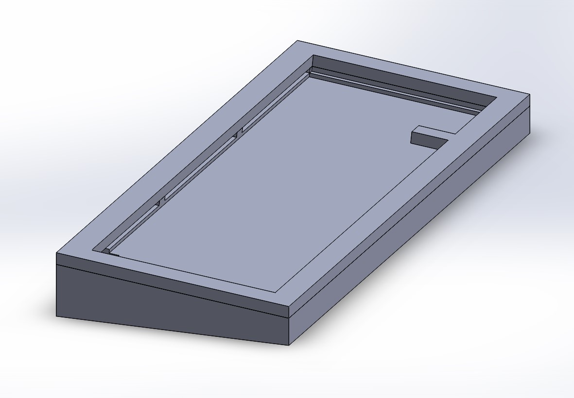
Then, I placed the mounting holes to join the two pieces together.
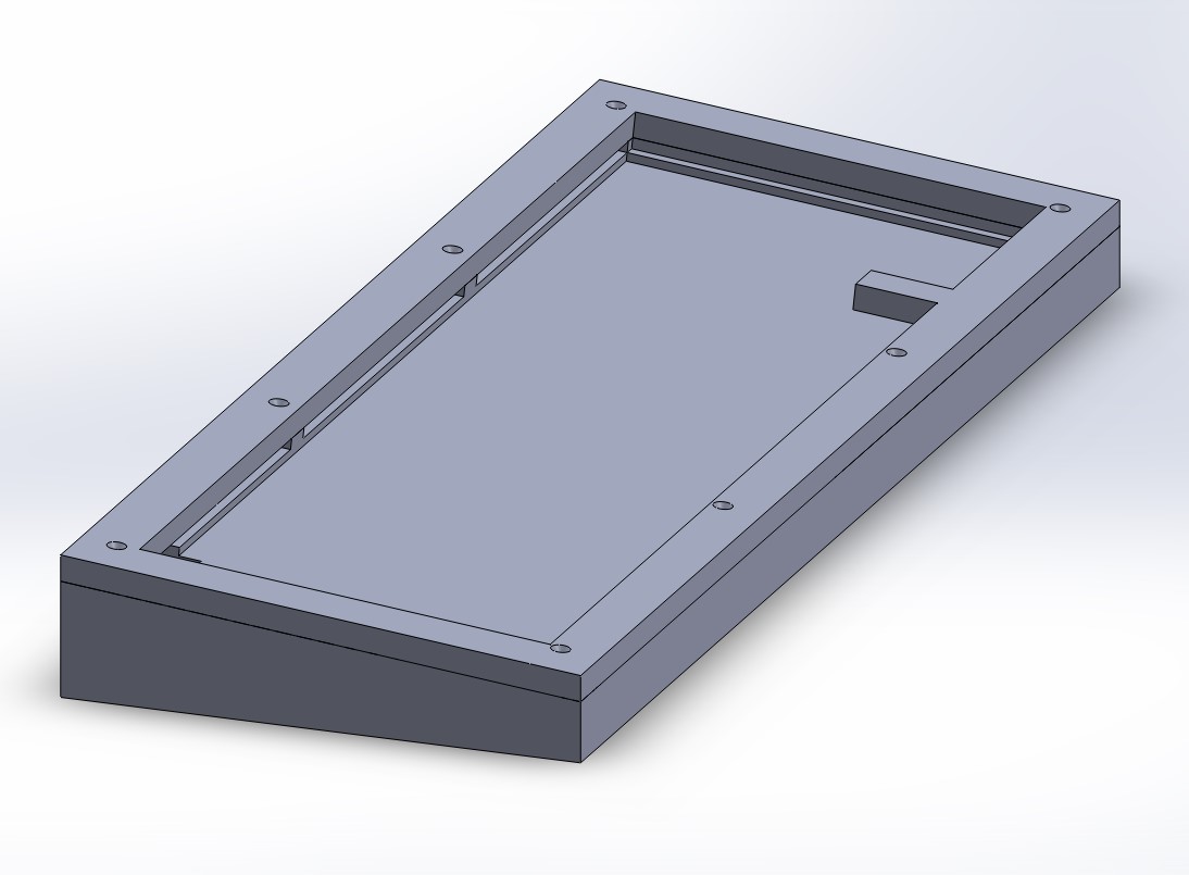
Then, more material in the middle of the board was cut out to reduce material cost and ensure the pcb have no clearance issues.
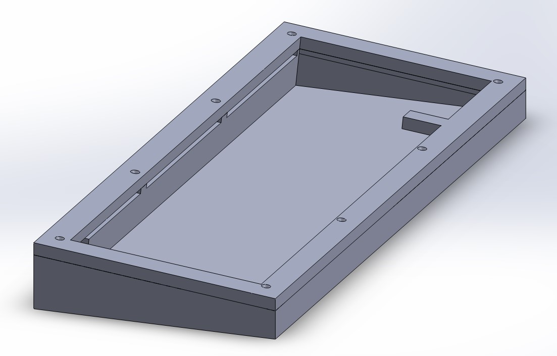
Finally, cutouts were placed at the bottom of the board to place rubber non-slip material for the case.
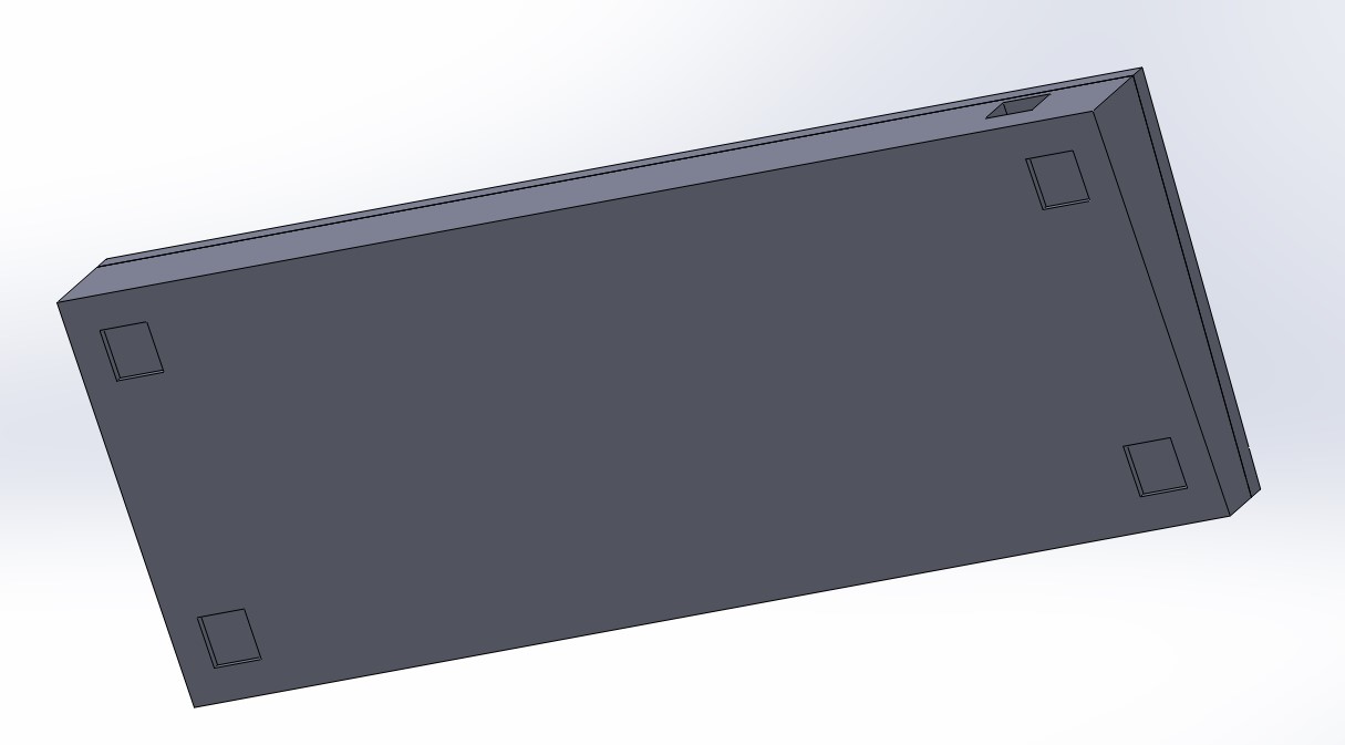
Plate
The plate design was much simpler as most of the hard work was done for me. The only design change I needed to before was adding a set of gasket mount wings to the the plate. As per my current plate, which I am basing the design on, the wings were a simple addition based on the dimensions. THe only thing I had to verify with the auto-generated plate was to confirm the placement of the key switches relative to the plate. For my current plate, the measurements lined up, which I suspect is because the seller I bought my current plate from used this plate builder. After this confirmation, I used AutoCAD to add the gasket supports, seen below.

Manufacturing
Plate
Manufacturing the plate was not so much of a challenge as I thought; the only issue was prototyping. With no readily source of laser cutter to me, I was forced to only manufacture the plate with an online source before testing.
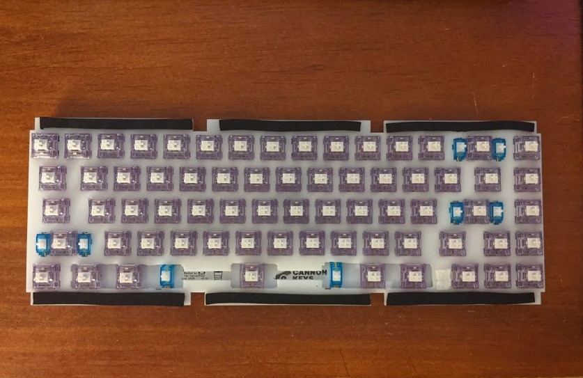
Of the places I shopped around for a manufacturer, I found https://www.sculpteo.com/ which was the best price and provided great manufacturing material for my needs. Some of the most common material types for keyboard plates denser materials such as aluminum, brass, or steel, and less dense materials such as carbon fiber, FR4, POM, and polycarbonate. Of these common materials, Sculpteo offered POM as the cheapest option, so I went with it. Unfortunately, the POM cuts Sculpteo offered where only in the 2mm thickness. This becomes an issue with switch compatibility. The usual MX style switches do not clip correctly into plates of thicknesses greater than 1.5mm, but this is fine as the max tolerance of plates for MX style switches are 5mm. Below is the plate that was manufactured by Sculpteo.
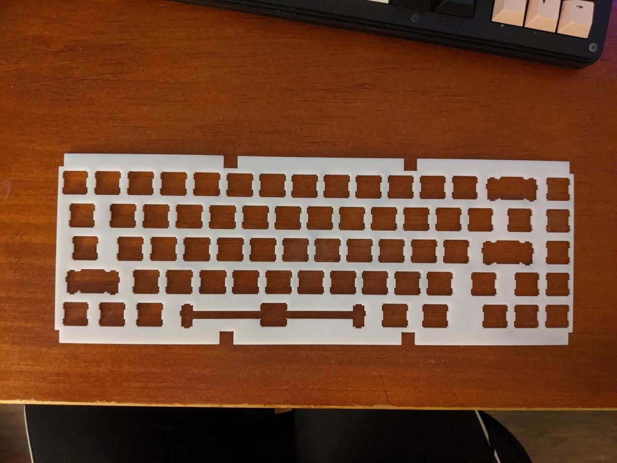
One unforeseen complication with ordering this part was flex in the plate. This issue caused the switches to sit in the PCB, but not mounted to the plate. Due to the mounting method I am using, switches not mounted correctly to the plate will cause issues, since the PCB is essentially floating. Thinking this would be an issue, I tried fixing this by leaving it in a stack of books for a few hours to try and straighten it out (with no success). Additionally, I thought about placing this stack on my heated print bed to help soften the plate, but I was afraid that I would warp the plate beyond use. I decided to just place all the switches into the plate, and jam material between the PCB and the plate to essentially hold the plate flat by constraining the plate and PCB to be a fixed distance at all points. This ended up being a great solution that need resolved the bending. Additionally, a major factor I overlooked was the alignment of switches to the plate. In the pictures below, we can see how almost the entire bottom row of keys are misaligned.
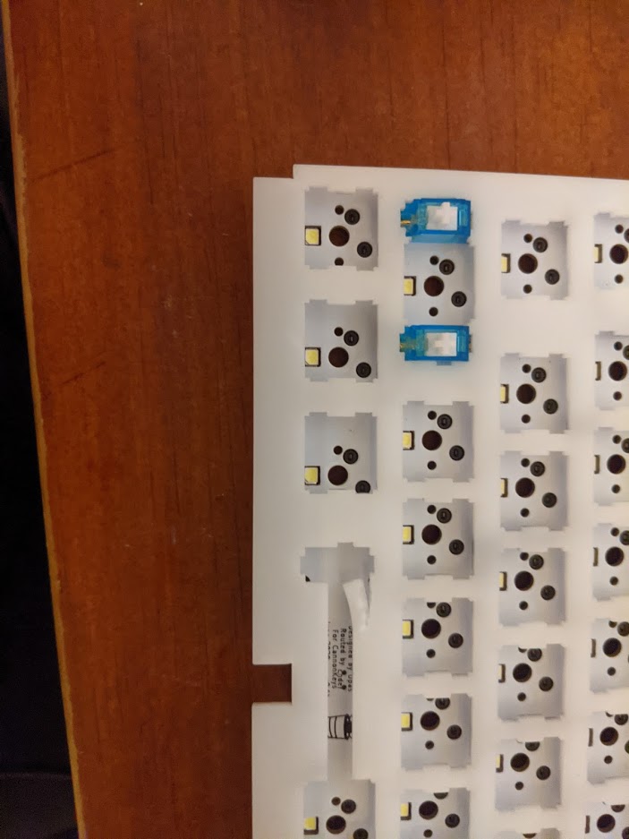
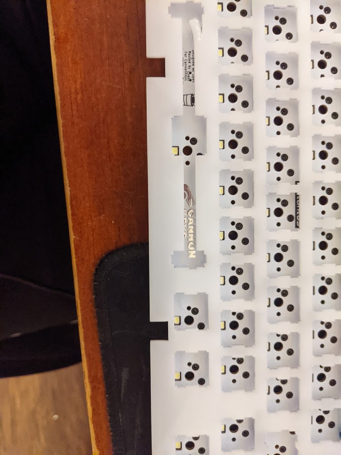
In order to get around this problem was just simply cutting the extra material to allow switches to be placed, seen below. In my final design, I redesigned the plate to remove this issue and to increase the PCB compatibility.
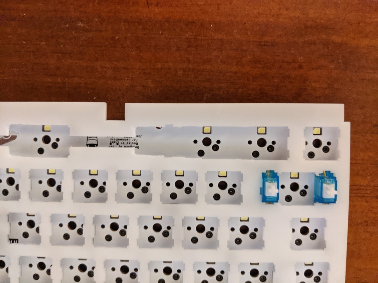
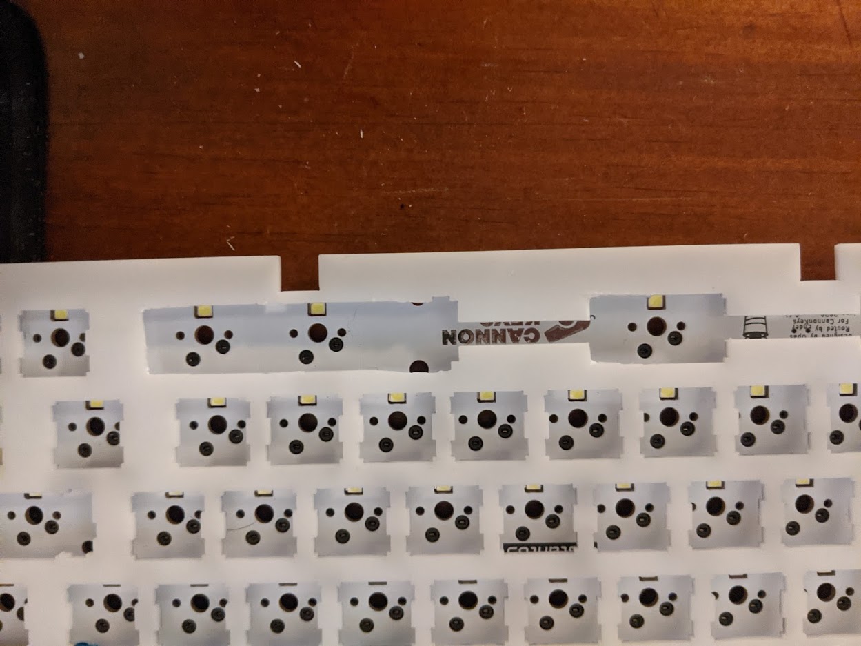
Finally, I was able to finish off the plate assembly by adding lavender linear switches and gasket material, which is a neoprene foam, seen on the fingers of the plate.
Case
With my end goal of machining this part using aluminum, I needed to print the board to test the fit and tolerances of my design. So, using my CR-10 V2, I printed the case. Unfortunately, the longest dimension of my build volume is the vertical height, so in order to print the entire case in one piece, I would need to stand the case on it’s side, seen below.
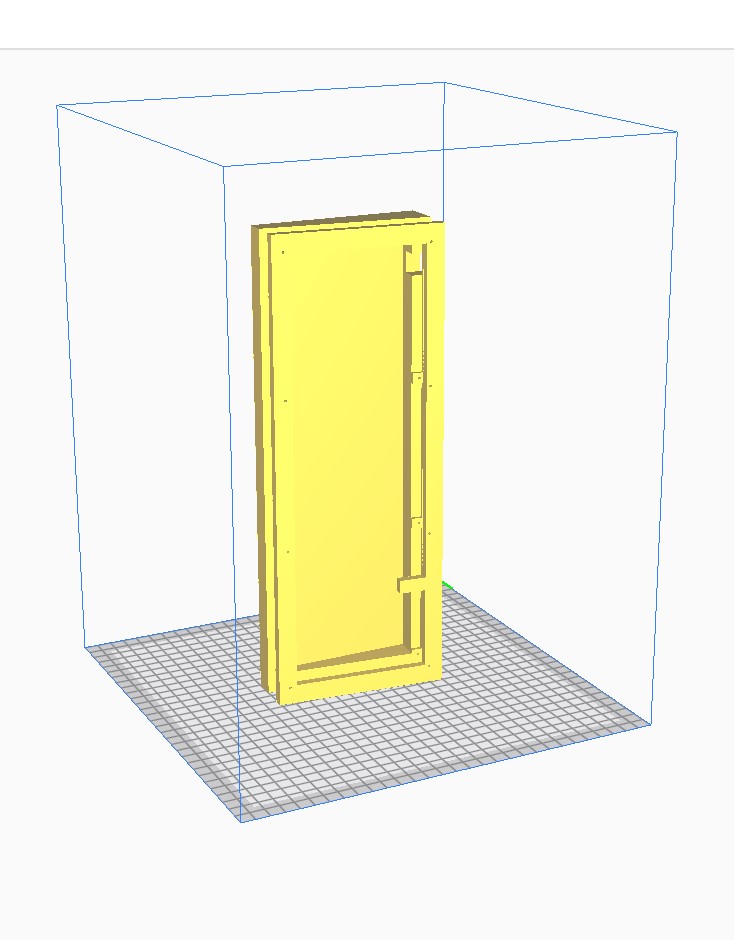
Obviously, this is terrible for print speed and stability, but this is was the only way I could prototype my design before sending it to be CNC’d.
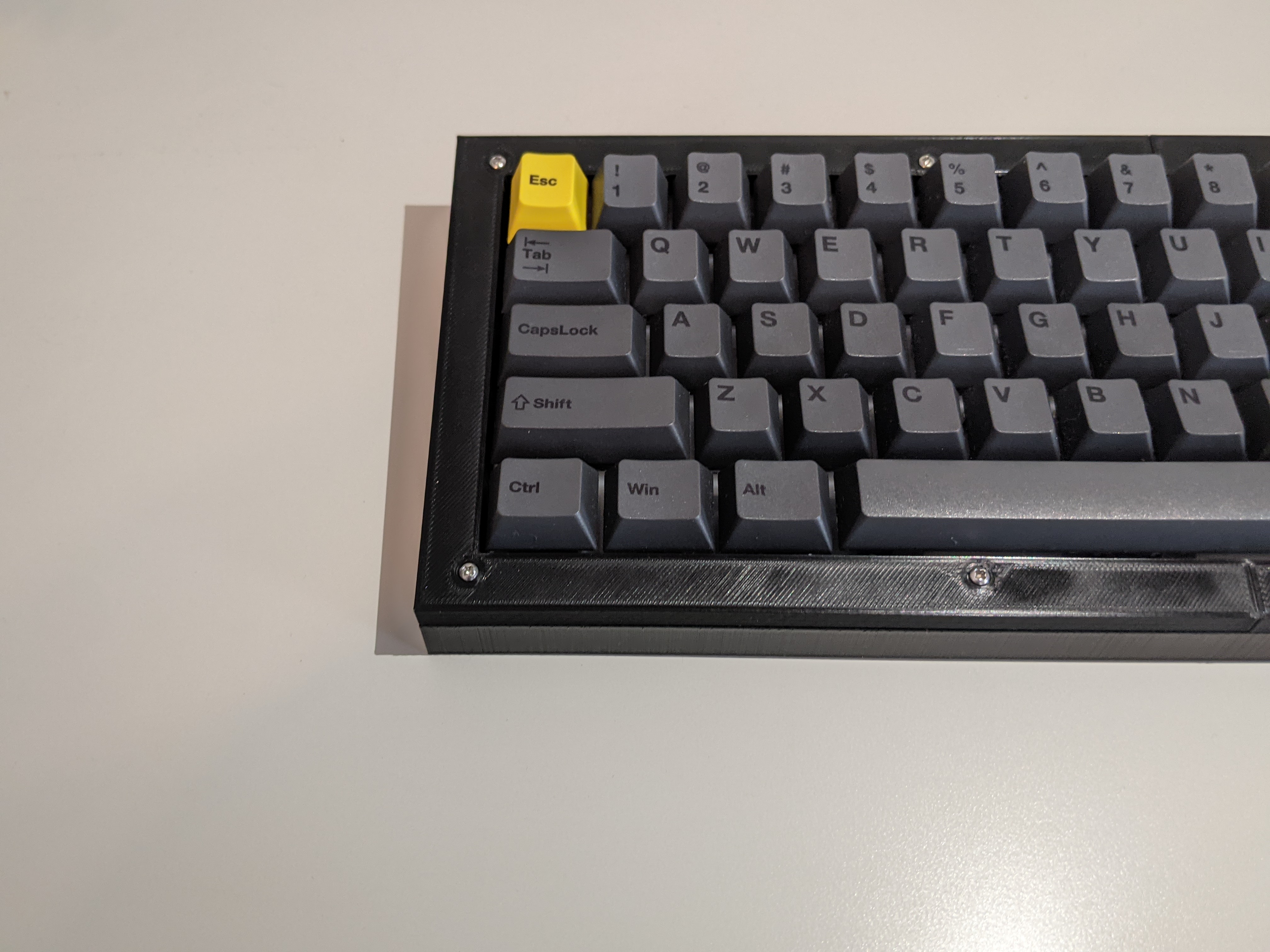
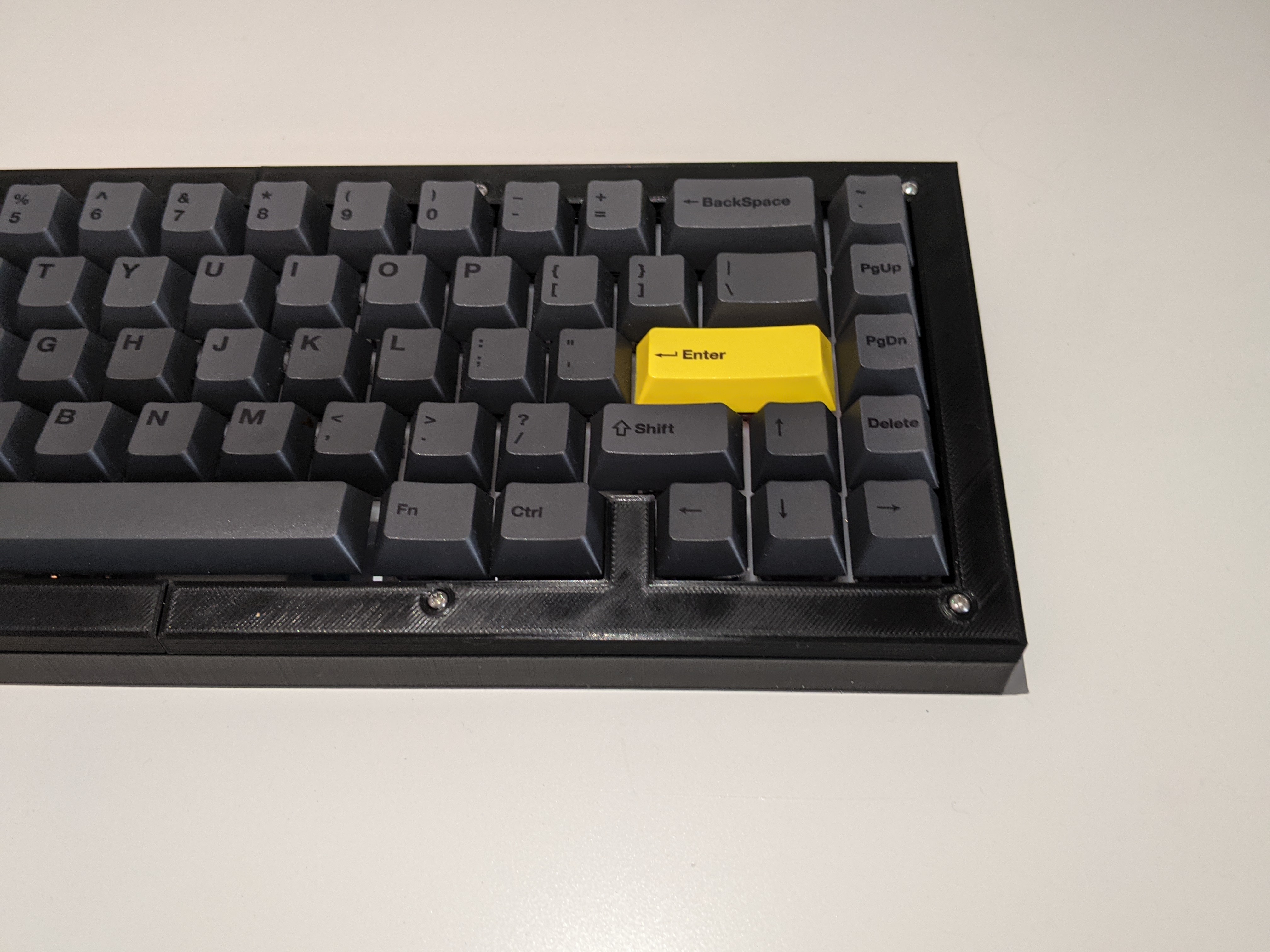
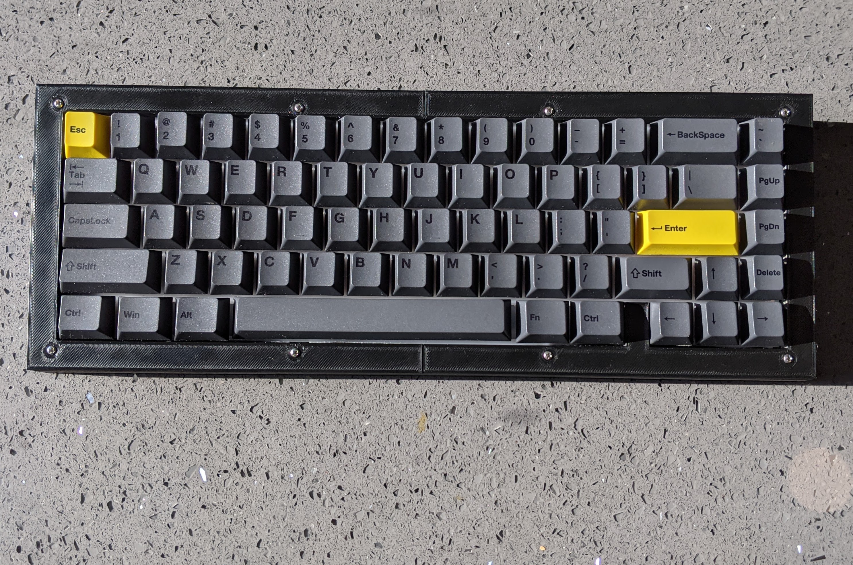
My first few prototypes were unsuccessful for a few reasons like incorrect measurements and print tolerance inaccuracies, but after a few hundred grams of PLA were used, I printed my first successful prototype!
Final Product
Reflections
This project has been very informative as it’s my first real fabrication project I have done by myself. Because of this I was able to learn so much about the fabrication and prototyping process. For example, I was able to fully see and learn how tolerances in designs are considered and made. I also learned a valuable lesson in prototyping; I didn’t mention it as much, but the total printing count before reaching a good print was 4. All of my other prints failed due to lack of build plate adhesion, artifacts that were created from the conversion of the SOLIDWORKS file to an STL, and finally running out of filament at 95% print completion! Each print took about 40 hours each to print on my printer, so if PLA filament wasn’t so inexpensive and wasn’t easy to manufacture, I could have potentially wasted even more time and money that I already did. In the future, I will definitely be more precise in my design and keep an more watchful eye on my prints and filament. Over all, I am immensely proud of myself and my design. Even though not many people would want to purchase a board I designed, and it isn’t the most innovative design, I will be this board whenever I can, and will be manufacturing an aluminum version of this case.
.jpg)

